The control and status registers share the odd address and the data buffer register uses the even address.The addressing is according to the following table:

         __   __   __
         CS   RD   WR   AO        Transfer description

         0    1    0    0       Data bus to data buffer register
         0    1    0    1       Data bus to control register
         0    0    1    0       Data buffer register to data bus
         0    0    1    1       Status register to data bus 
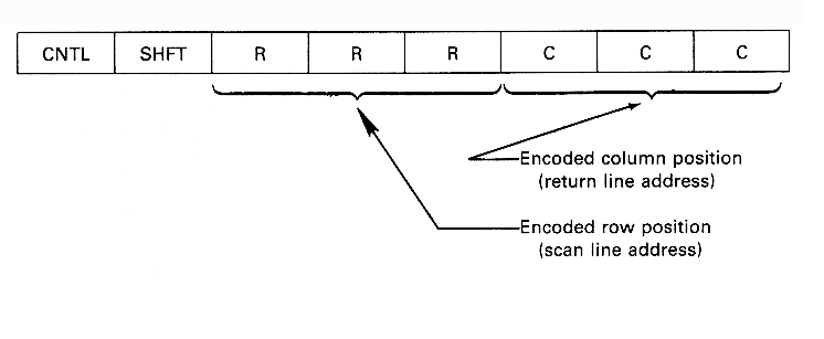
For keyboard control, the 8279 constantly scans each row of the keyboard by sending out row addresses on SL2-SL0 and inputting signals on the return lines RL7-RL0, which represent the column addresses.


When a depressed key is detected, the key is automatically debounced by waiting 10 ms to check if the same key remains depressed.If a depressed key is detected an 8-bit code word corresponding to the key position is assembled by combining the encoded column position, row position, shift status and control status as shown below.

The SHIFT and CNTL pins are used primarily to support typewriter-like keyboards which have shift and control keys.The key position is then entered into the 8x8 first-in/first-out (FIFO) sensor memory and the IRQ (interrupt request) line is activated if the sensor memory was previously empty.
The three MSBs of a command determine its type and the meaning of the remaining 5 bits depends on the type.Although there are eight types, only three of them are considered here.

PRETHODNA FOLIJA SADRZAJ SLEDECA FOLIJA