Tutorial Contents
Introduction
Starting
Active-VHDL
The
Framework
Creating
a New Design
Design
Browser
Editing
Code
Checking
Syntax
Adding
Files to a Design
Creating Top-Level File
Viewing the Design Structure
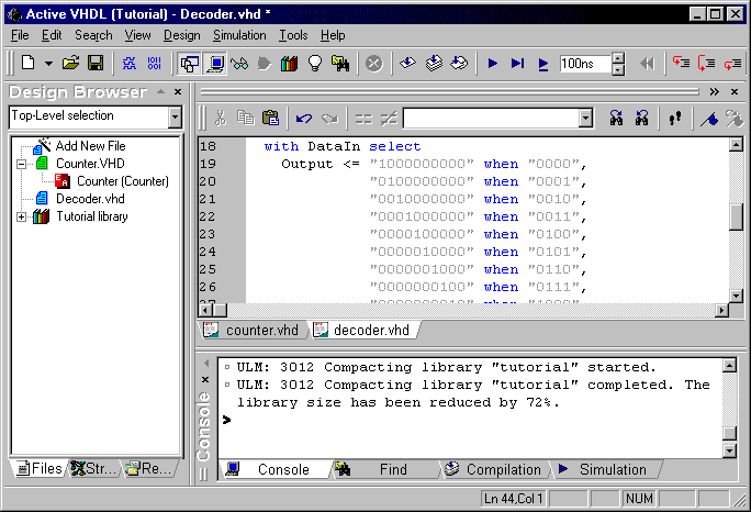
Viewing
Local Data
Simulation
Adding
a Test Bench
Running
Test Bench
Welcome to the ALDEC newest product – Active-VHDL.
The tutorial will guide you through the amazing world of the integrated VHDL tools.
This tutorial requires basic knowledge of VHDL. If you have none, ALDEC’s
InterActive-VHDL Tutorial will be a good starting point. Its preview is available on
www.aldec.com.
To start working with the program go to the Start->Programs->Active-VHDL
program group and click the Active-VHDL label. The Active-VHDL should start
loading.
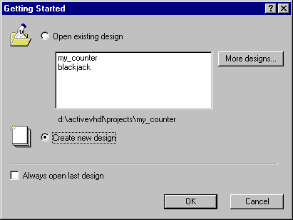
When the loading process finishes the following dialog appears:
Ensure that the Create new design option is checked and click the OK button. It will start New Design Wizard.
The Active-VHDL framework is based on a standard MFC-like GUI interface. Each window can be dockable, overlapped or application-like.
The main parts of the Active-VHDL are:
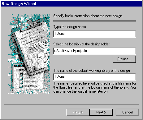
Entering the name of a design
Active-VHDL features an easy-to-use New Design
Wizard.
Checking the Create new design option in the welcome dialog will invoke the
wizard.The first dialog allows entering a design name and a directory name where
design’s files are to be placed.
Specifying the contents of a design
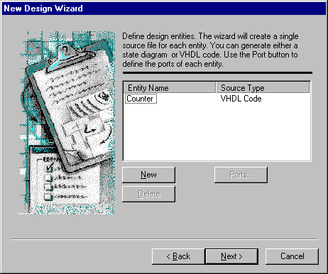
The next dialog lets you specify the contents of the design you are creating.
You can:
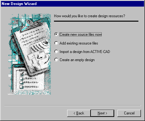
Creating the skeletal source file
In the following dialog you can add components you want your design to be comprised of.
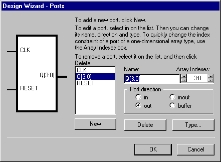
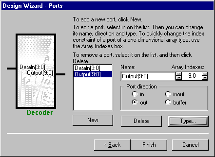
Ports Wizard
Ports Wizard is a useful tool for entering ports.
What you need to do is to click the New button and type a port name in the Name
box.
You can specify the direction of a port using the Port direction controls.
If you want to enter a bus, you can set its range in the Array Indexes box.
- CLK - input port
- RESET - input port
- Q[3:0] - output bus port , range [3:0]
Accepting the properties of a design
The last dialog is a confirmation dialog. Your design
properties are displayed in this window. If they are correct, click the Finish
button. Use the Back button if the settings are incorrect.
Use the Cancel button if you don’t want to create the new design.
Click the Finish button to complete the design creation.
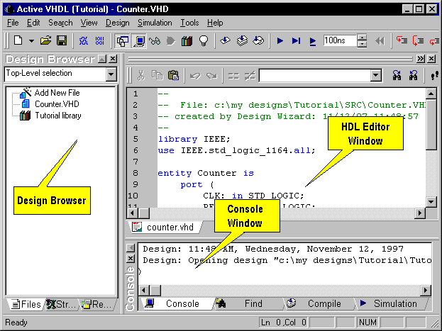
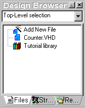
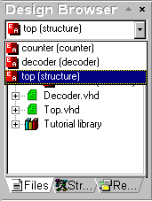
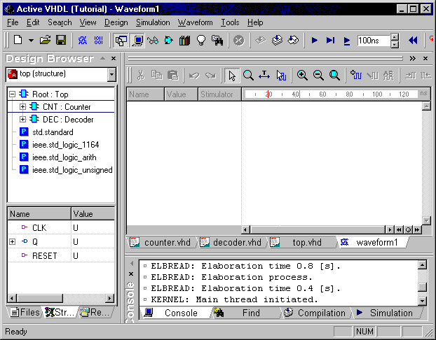
The next paragraph introduces the Design Browser.
The Design Browser is a window showing the design
contents.
As a result of the previous operations you will receive the following window:
Select the Counter.vhd file in Design Browser to highlight the source file name. Select Compile from the Design menu and watch the changes in the Design Browser window.
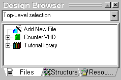
Click the "+" sign to expand the view.
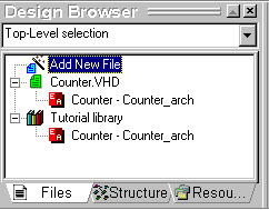
The window shows an entity-architecture pair.
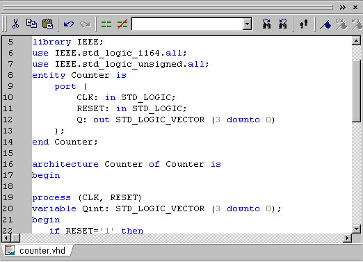
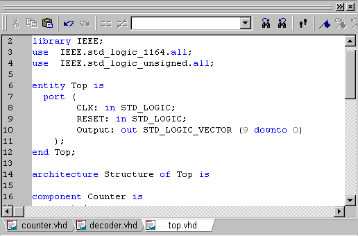
Double-click the Counter.vhd label to invoke the HDL Editor.
HDL Editor
The HDL Editor is a text editor with VHDL keywords coloring and standard editing features.
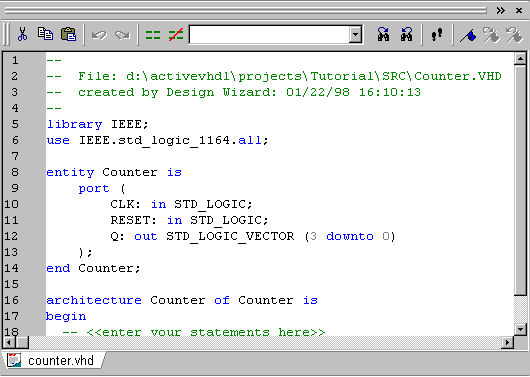
If you have followed all the steps you will see the window
above.
The generated code is a template based on your port settings.
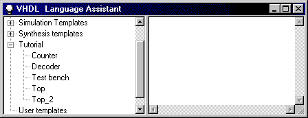
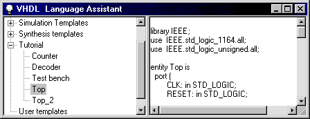
Language Assistant
Let’s describe the structure of the "Counter" now.
Open the Language Assistant using the approriate option from the Tools menu.
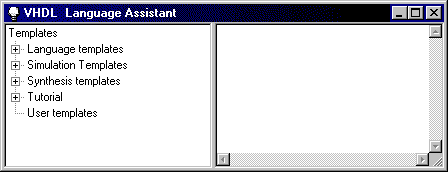
Expand the Tutorial label.
The following items will appear:
Click the Counter label.
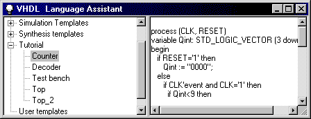
In the above preview window there is a VHDL process
description of a BCD counter.
Now, we will paste the template into the code.
Adding libraries
The edited code requires some additional packages to be
included.
The following line has to be added after the use IEEE.std_logic_1164.all:
use IEEE.std_logic_unsigned.all;
The result is:
You have just edited the "Counter" unit.
Go to the Design Browser window, select Counter.vhd label and click the right mouse-button. Choose the Compile option from the shortcut menu.
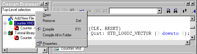
If there is any error, the icon changes to yellow,
erroneous line is underlined and the VHDL console window contains the error description.
If you want to see how errors are displayed, delete the first letter from the library
statement and run the compilation.
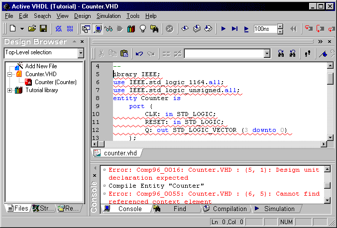
Re-type the letter to reverse to the previous error-free state.
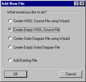
To add a file, you have to choose the New ->VHDL Source item from the File menu, or double-click the Add New File label in the Design Browser tree. The following dialog appears asking you to select the way the new file will be added to the design.
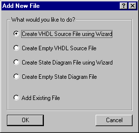
Select the Create VHDL Source File Using Wizard
option, and then click OK.
The New Source File Wizard is invoked.
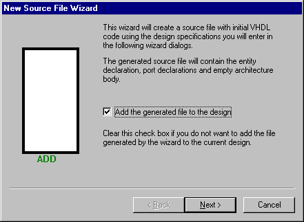
Press the Next button.
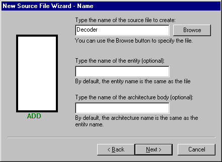
In the wizard’s window shown above, type Decoder
as the name of the file.
Click the Next button to advance to the next page.
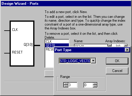
Enter ports as shown in the window above. Select the STD_LOGIC_VECTOR
type for each port.
Click the Finish button to complete the operation.
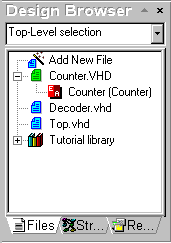
The Design Browser shows:
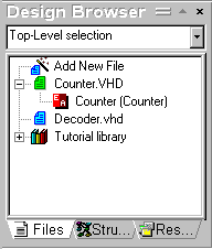
We have created two separate designs contained in the
"Counter.vhd" and the "Decoder.vhd" files.
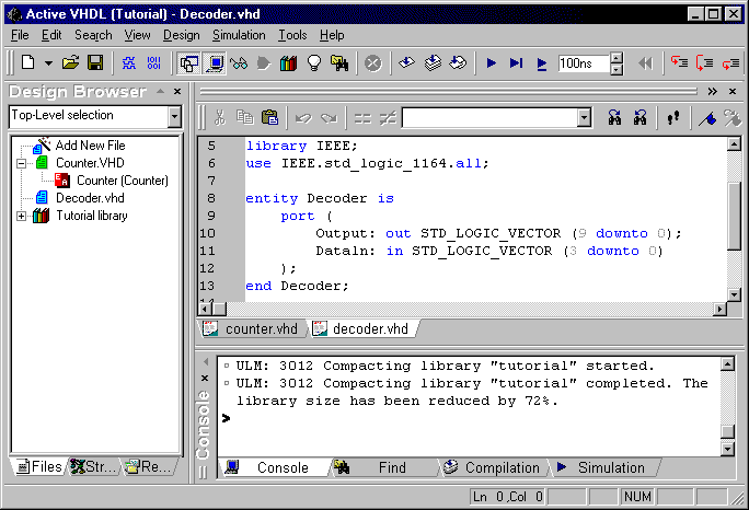
Double-click the Decoder.vhd to show its VHDL source.
Now, we will fill in the architecture template using Language
Assistant.
In the Language Assistant window, go to the Tutorial item and select the Decoder
label.
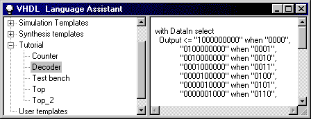
Place the cursor in the architecture block after the
begin statement in the HDL Editor window, select the Decoder label
and select Use from the shortcut menu.
The window contents should be as follows:
The Design Browser contents after the above operations is shown below:
The HDL Editor contents:
Let’s now recompile the entire design.
Use the Compile All option available in the right-button pop-up menu.
Next, you have to specify your top-level entity.
Press the pull-down list's button to see the available entity-architecture pairs. Select
the "top-structure" label.
You can do the same operation by selecting the "top-structure" label in the tree and choosing the Set as Top-Level option available in the right-button pop-up menu. You can also use the Settings command available under the Design menu. This will display the Design Settings dialog in which you can select the top-level entity on the Top-level Selection tab.
Go to the Design Browser and select the Structure tab:
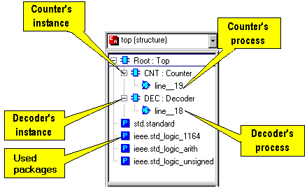
The Structure tab shows the structure of a design.
In the Top design, which has the Root attribute, there are two components
instantiated: Counter and Decoder.
Each of these components has one process, which is shown in the tree. Also all the used
packages are shown.
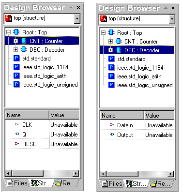
Each design unit can contain ports, signals and variables.
Active-VHDL allows easy browsing through the unit data.
If you click a component label on the Structure tab of the Design Browser,
its local data will be displayed in the lower pane of the window.
Let’s verify our design.
Starting simulation
To begin a simulation, you have to first initialize the
simulator using the Initialize Simulation option from the Simulation
menu.
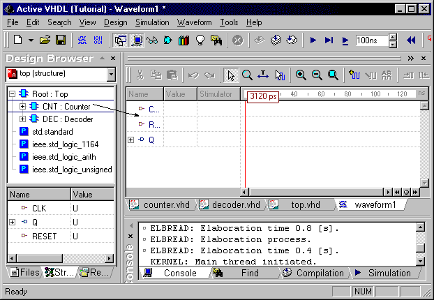
After the simulator has been initialized, you have to open a new Waveform window.
Click the New Waveform toolbar button ![]() .
.
The new Waveform window appears.
Signals for simulation can be added using the drag and drop
feature.
On the Structure tab of the Design Browser you have to select the component
whose ports you want to observe and simply holding the left button, drag it to the
left-hand section (pane) of the waveform window and release the button (typical
drag-and-drop operation).
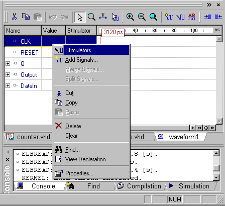
If you want to delete a signal, select it and press the right-button. A pop-up menu comes up containing the Delete item. Choose this option to delete the signal.
Code source tracking
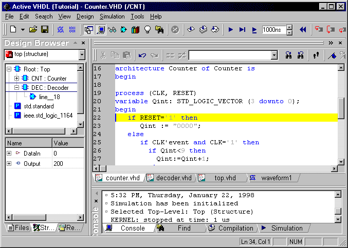
Active-VHDL allows walking along the code during the step simulation. The code window is automatically opened after the one of the step simulation buttons has been clicked. The statement which is to be executed next is yellow highlighted in the HDL Editor window.
There are three commands for step simulation:
| The Simulation /Trace Into command executes a single VHDL statement. If a subprogram call is encountered, the execution descends into the subprogram body. | |
| The Simulation /Trace Over command executes a single VHDL statement. If a subprogram call is encountered, the statements contained within the subprogram body are skipped. | |
| The Simulation /Trace Out command completes the currently executed subprogram. If subprograms are nested, the command completes the innermost subprogram only. |
Click one of the two toolbar buttons: View Watch Window
![]() and View Processes Window
and View Processes Window ![]() to see the additional windows – Watch and Processes.
to see the additional windows – Watch and Processes.
The Processes window shows the status of design processes.
The Watch window enables you to examine values of signals and variables during
simulation.
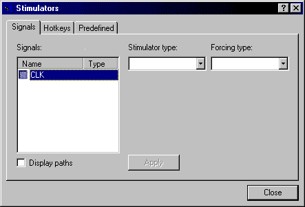
Assigning stimulators
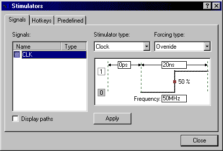
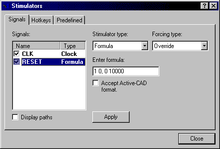
Lets’ simulate!
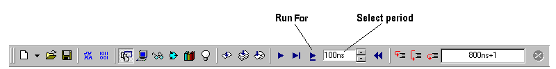
You can perform either a single step simulation, which is useful for source code debugging, or a continuous simulation, for high-speed design analysis and comparing results. See the picture below:
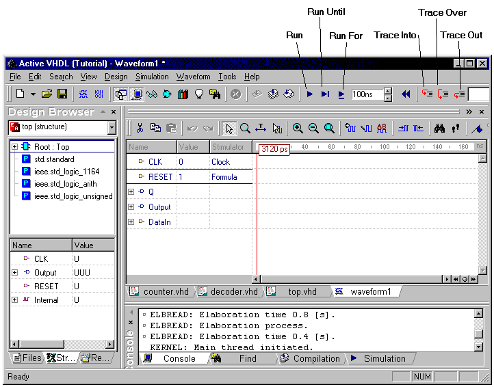
Perform several simulation steps by clicking on the Trace
Over button. Click the Run For button.
You will receive the following results on the waveform tab.
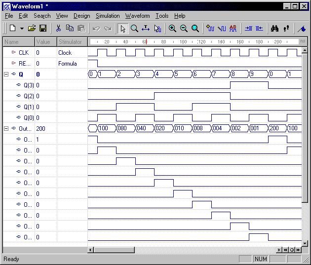
The Output bus has been expanded by clicking the
"+" sign next to the label.
You can press e.g. Decoder.vhd tab in the HDL Editor window to see the code
being debugged.
Finish the simulation using the End Simulation option in the Simulator menu.
In this chapter you will add a test bench which is a testing environment for our design.
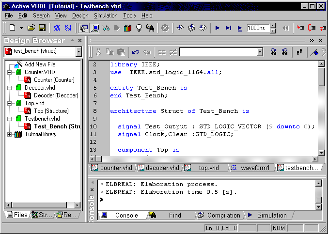
Test bench contains components that drive design’s
inputs to obtain results.
To perform these steps you must first delete the signals from the Waveform window,
because the test bench will drive the Clock input and the Reset input by
itself.
Then add them back by dragging component Project: Top to the Waveform window.
You need only to press the Run For button several times.
The results are:

Thank you for using Active-VHDL !