Creating FPGA /CPLD Designs with Active-VHDL
Introduction
This application note describes a typical approach to FPGA and CPLD designing in Active-VHDL. The document does not focus on any specific FPGA or CPLD vendor. Detailed guidance on designing for different vendors is the subject of vendor-specific tutorials.
Resource Files
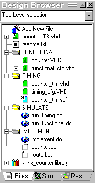
A typical FPGA /CPLD design contains resource files (source files, SDF files, macro files, etc.) created at different stages of the design process. To clarify the design contents, consider dividing the resource files into groups stored in separate folders in the Design Browser. An exemplary grouping can be as follows:
- Structural VHDL files modeling the physical netlist.
- SDF files containing timing data used to annotate timing models.
The Design Browser allows you to create any number of folders with any names. The name of a folder does not imply its destination.
The figure below shows the folders as discussed in the text.
Functional Simulation
The initial VHDL description of the design undergoes functional verification in the VHDL simulator. The key issue at this stage of the design process is creation of appropriate test vectors. Test vectors provide stimulus for the model inputs and forces the model to produce the output response. Evaluation of the output response provides the answer to whether the model’s behavior satisfies the designer’s expectations or not.
In Active-VHDL, you can apply stimulus to the input models in three different ways:
Creating Test Benches
The figure below illustrate the concept of a test bench.
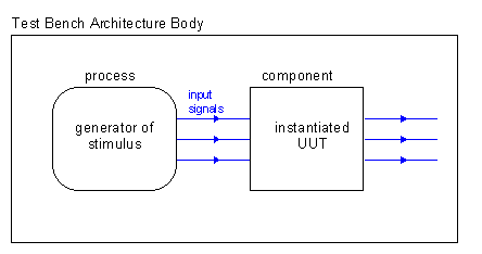
The process implemented in the architecture body of a test bench should force desired stimulus on the inputs of the tested design unit (Unit Under Test = UUT) to enable functional verification of the design. In addition, advanced test benches can also perform comparison of the obtained output response with a previously defined pattern.
Active-VHDL supports automatic generation of test benches on the basis of waveforms previously created in the Waveform window and saved to a file. The test bench file contains a test bench entity declaration and its architecture body. The architecture body contains:
It is usually possible to re-use in timing simulation a test bench created for functional simulation. The shortest way to do so is to write a configuration declaration that binds to the UUT entity the architecture body obtained from the Place and Route tool. Such an approach is applicable only if the entity obtained from the Place and Route tool matches the UUT entity in the initial VHDL description in respect of ports and generics.
Synthesis
After the design has been verified in functional simulation, it should be synthesized in order to obtain a netlist for physical implementation. Active-VHDL itself does not provide any interface to synthesis tools. However, the user can write macros that will call external programs and pass data to and from them. Moreover, it is possible to extend the macro language by adding user-defined basic scripts that implement new commands. In this way, it is possible to create a user-customizable interface to external synthesis and Place-and-Route tools. The only restriction arises from the fact that the external programs are called along with parameter specification from the command line. Not all programs can work in such a mode.
Different synthesis tools have their specific sets of options. The information of these options is available in proprietary documentation for these tools.
Some synthesis tools can export synthesized netlist into VHDL. Simulation of so obtained VHDL code and comparison with results from the simulation of the initial description gives you additional verification of the design.
Active-VHDL can be used along with Active CAD. Active CAD provides interface to a variety of synthesis and Place and Route tools in a wide range of vendors (Actel, Altera, Lucent, Lattice, QuickLogic, Xilinx) and target devices. Active CAD can export a project into VHDL. During the export, the project netlist (pre-routed) is converted into VHDL and a new design is created in the Active-VHDL-compatible format.
Implementation
The netlist produced by synthesis tools is an input for Place and Route tools. The final result of running of a Place and Route tool is a bitstream file that can be downloaded into a programmable FPGA device. Most tools can generate VHDL model of the implemented design for timing simulation. The model is structural and based on primitive models supplied in the vendor-provided VHDL libraries. Appendix A provides a list of vendor-specific libraries shipped with Active-VHDL.
Most libraries with timing primitive models are based on VITAL procedures.
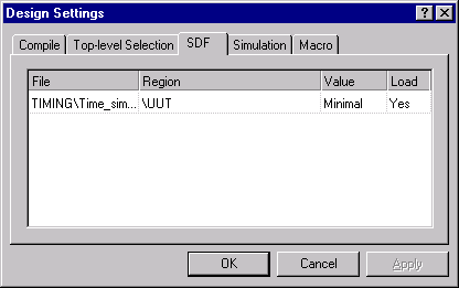
Primitive models used for timing simulation possess a set of timing parameters (passed on to the model through generics). Two methods are applicable to define value of these generics:
Adding Post-Place-and-Route Files to Design
Using the Design Browser you have to attach to the design the files obtained from the Place and Route tool. These files usually are:
You can also create a brand new design for files obtained from the Place & Route tool.
Compiling of Post-Place-and-Route VHDL Code
The VHDL file generated by Place-and-Route tools contains an entity-architecture pair (design entity) describing the design implemented in an FPGA /CPLD device. In general, the entity and architecture in the generated file can have any names. Note that if these names are identical to those of the design units in the initial design description, compilation of the post-Place-and-Route files will cause that some design units will be overwritten in the default design library.
It is also important that the ports of the post-Place-and-Route entity matches those of the entity in the initial description.
Timing Simulation
To simulate the timing model obtained from the Place and Route tool, you have to:
Note that SDF annotation must be performed before initialization of simulation.
Creating VHDL for Synthesis
- Synthesis tools impose specific constraints on the range of available VHDL constructs and contexts in which they can appear.
- Synthesis tools infer the logic also from the context in which specific VHDL constructs appear.
Appendix A
Vendor-specific libraries of simulation primitives
ACTEL
A3200DX - functional and post-place-and-route simulation library for 3200DX family
ACTEL1 - functional and post-place-and-route simulation library for ACTEL1 family
ACTEL2 - functional and post-place-and-route simulation library for ACTEL2 family
ACTEL3 - functional and post-place-and-route simulation library for ACTEL2 family
ALTERA
ALT_VTL - post-place-and-route simulation library
CYPRESS
CYPRESS_FUNCTIONAL (for CPLD/ FPGA) - functional component library with arithmetical packages.
PRIMITIVE (for CPLDs) - post-place-and-route simulation library
QLPRIMS (timing models for PASICs) - post- place-and-route simulation library
LATTICE
LAT_VHD - functional component library
LAT_VITL - post-place-and-route simulation library
LUCENT
ORCA - functional component library
NEOPRIMS - post-place-and-route simulation library
Quick Logic
QLOGIC_FUNCTIONAL - functional component library
QLPRIMS - post-place-and-route simulation library
XILINX
XU - functional component library
SIMPRIM - post-place-and-route simulation library
Except for CYPRESS_FUNCTIONAL and PRIMITIVE, all libraries mentioned above are based on standard VITAL procedures and are shipped with the vendor’s software.
Appendix B
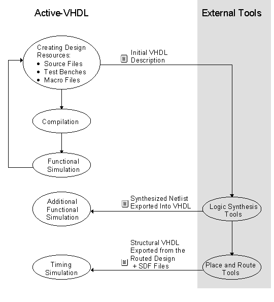
Block Diagram of Processing of FPGA /CPLD Designs