For a system that contains an 8237 DMA controller, the 8288 would replace the circuit for encoding the \RD,\WR and IO/ \M signals shown in Fig.9-38 and detailed in Fig.9-39.In any event, with the inclusion of an 8288 the \RD and \WR pins on the interfaces would be attached to the \IORC and \IOWC outputs from the 8288 and the IO/ \M lines shown entering the address decoders would no longer be required.
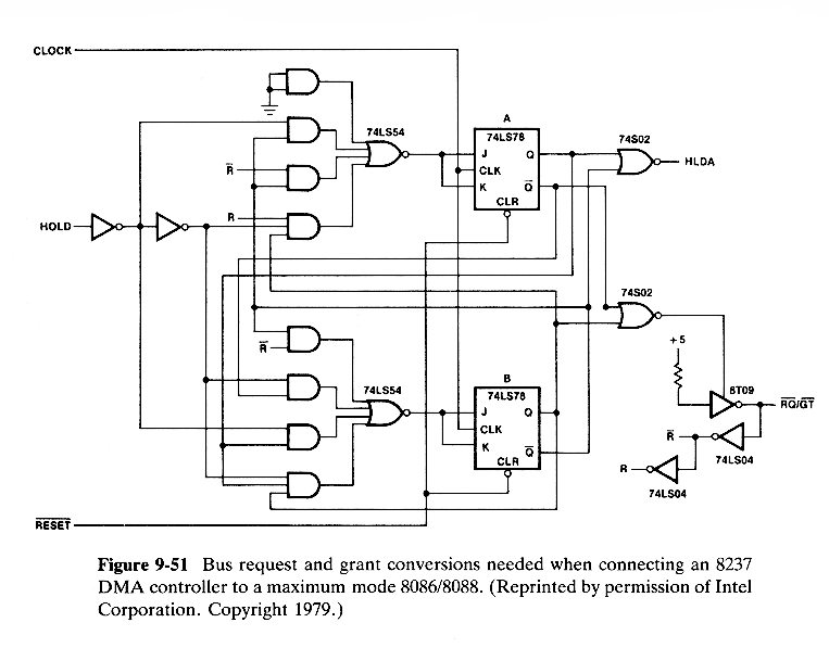
The other major change concerns the HRQ and HLDA signals used to make bus requests and grants.The 8237 is designed to output a continuous request HRQ signal until it is ready to relinquish the bus, at which time it drops the signal.Also, the processor outputs a continuous HLDA signal. This is compatible with n 8086/8088 processor in minimum mode, but in maximum mode the processor uses a single \RQ / \GT line to both receive requests and issue grants and expects to see only a pulse at the time the request is made.The request is acknowledged by outputting a pulse and a second pulse must be sent to the processor from the DMA controller at the conclusion of the DMA activity.
A circuit for converting between the two-line continous signals associated with the 8237 and the one-line pulses of a maximum mode processor is given in Fig.9-51.
